
ZK-PP1 Dual Model Signal Generator Square Wave 1Hz-150KHz PWM Pulse Generator Module Frequency Duty Cycle Adjustable
Product details
| Management number | 220366071 | Release Date | 2026/05/03 | List Price | $15.52 | Model Number | 220366071 | ||
|---|---|---|---|---|---|---|---|---|---|
| Category | |||||||||
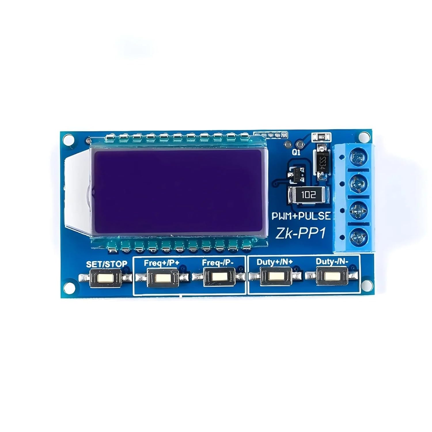
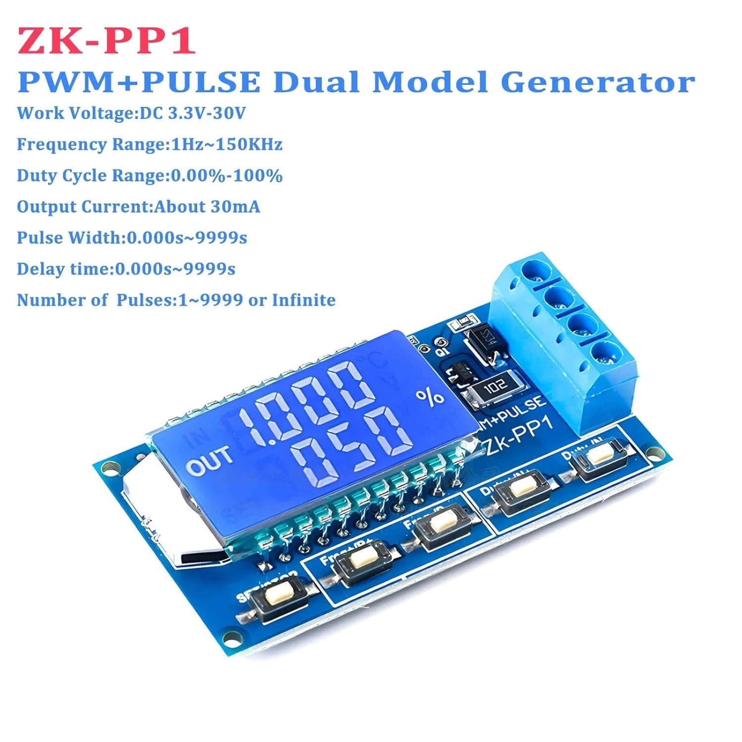
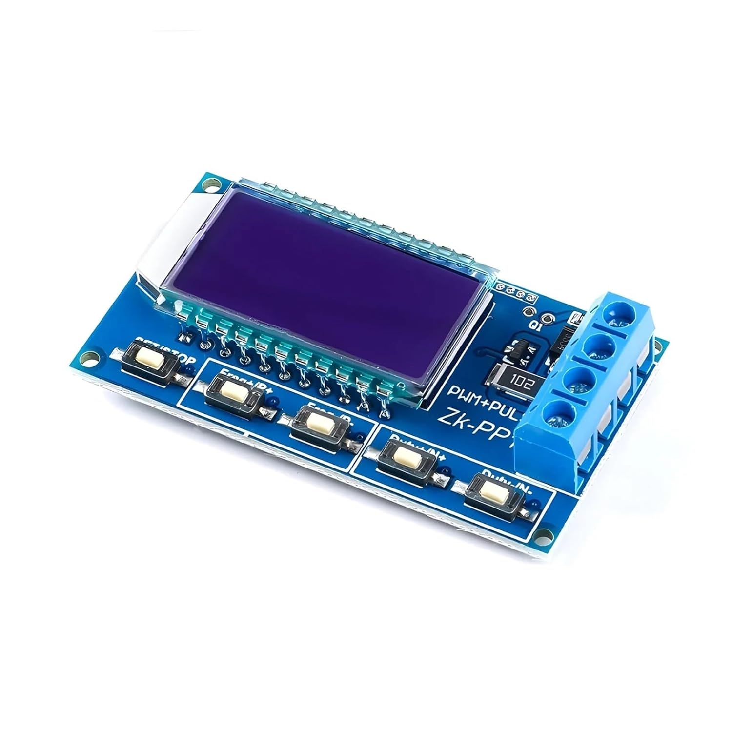
Digital Signal ProcessorsZK-PP1 Dual Model Signal Generator Square Wave 1Hz-150KHz PWM Pulse Generator Module Frequency Duty Cycle Adjustable 1.Description:ZK-PP1 signal generator is a device that provides electrical signals at a variety of frequencies, square wave,pulseand output levels.It supports dual mode:PWM mode and PULSE mode.It is used as a signal or excitation for testing.Widely used in production practice and technology.2.Features:1>.Dual mode:PWM mode and PULSE mode2>. high definition display3>.Support frequency adjustment4>.Support duty cycle adjustment5>.High precision detection6>.Support power-down memory function7>.1-Channel signal output8>.Support reverse protection3.Parameters:1>.Product name: ZK-PP1PWM Signal Generator2>.Model: ZK-PP13>.Work voltage:DC 3.3V-30V4>.Frequency range:1Hz~150KHz5>.Frequency accuracy:2%6>.Duty cycle range:0.00%-100%7>.Output Current:About 30mA8>.Number of pulses:1~9999 or Infinite9>.Delay time:0.000s~9999s10>.Pulse width:0.000s~9999s11>.Time accuracy:1ms12>.Output amplitude:Same to input voltage13>.Work Temperature:-40~8514>.Work Humidity:0%~95%RH15>.Size:60*32*13.5mm4. Work Mode:1>.PWM Mode:Frequency,Duty cycle1.1>.It is PWM mode when display '%'.1.2>.The default mode is PWM mode.1.3>.Button FREQ+ and FREQ- are used to setting output frequency.User can short press by set value in minimum unit or keep press to continuous setting. Frequency range is 1Hz to 150KHz.1.4>.Button DUTY+ and DUTY- are used to setting output duty cycle for frequency.User can short press by set value in minimum unit or keep press to continuous setting. Duty cycle range is 0.00% to 100%.1.5>.Short press button 'STOP'to enabled or disabled output.It is enabled output when display symbol 'OUT'on left.It is disabled output if no display symbol 'OUT'and module will output 0V.1.6>.The default frequency is 1KHz and the duty cycle is 50%.1.7>.Switch work mode:Keep press button 'SET'about 6 second.The it is enter into PULSE mode if symbol '%'disappear on right.2>.PULSE Mode:Pulse width,Delay,Pulse number2.1>.It is PWM mode without display symbol '%'.2.2>.Button P+ and P- are used to set time for positive pulse width.Displayed on the first line.Set time range is 0.000s~9999s.2.3>.Button N+ and N- are used to set time for negative pulse width time.Displayed on the second line.Set time range is 0.000s~9999s.2.4>.Short press button 'STOP'to enabled or disabled output.It is enabled output when display symbol 'OUT'on left.It is disabled output if no display symbol 'OUT'and module will output 0V.2.5>.The default positive pulse width is 0.5 seconds, and the negative pulse width is 0.5 seconds.2.6>.Long press button 'SET'for 2 seconds to enter into set the number of pulses and delay time.Screen will display symbol 'SET'at lower left corner.Note:Once in this mode,the output will be disabled and output pulse will be cleared.2.7>.Button P+ and P- are used to set delay time.Set time range is 0.000s~9999s.2.8>.Button N+ and N-are usedset the number of pulses.Set range is 1~9999 or Infinite.2.9>.The default delay time is 0 seconds, and the number of pulses is infinite (display '----').2.10>.Automatic to pulse interface by press button 'SET'for 2 seconds.2.11>.Short press button 'STOP'to delay the set time and start output the set number of pulses.2.12>.It will automatically output 0V if the number of pulses is sent.The output will be disabled and clear pulse numbers if press button 'STOP'during output.2.13>.The number of set pulses is output each time when module power on.5.Practical Application:1>.PWM output 20KHz,60% : Select PWM mode.Set frequency to 20.00 and duty cycle to 060%.2>.Output turn ON 0.6s,OFF 0.2s,infinite loop : Select PULSE mode.Set positive pulse width to 0.600 and negative pulse width to 0.200.Delay time to 0.000.Number of pulses to '----'.3>.Delay 5s after power ON or press 'STOP'button.Then output turn ON 0.6s,OFF 0.2s,infinite loop : Select PULSE mode.Set positive pulse width to 0.600 and negative pulse width to 0.200.Delay time to 5.000.Number of pulses to '----'.4>.Delay 5s after power ON or press 'STOP'button.Then output 10ms high level signal,10ms low level signal,cycle 100 times : Select PULSE mode.Set positive pulse width to 0.010 and negative pulse width to 0.010.Delay time to 5.000.Number of pulses to 0100.5>.Delay 5s after power ON.Then keep output : Select PULSE mode.Set positive pulse width more than 0(any value) and negative pulse width to 0.000.Delay time to 10.00.Number of pulses to '----'.6.Use Steps: 1>.Connect to power supply.2>.Select work mode as following manual.3>.Short or long press button 'FREQ+'or 'FREQ-'to set parameter.4>.Short or long press button 'DUTY+'or 'DUTY-'to set parameter.5>.Connect to load.7.Application: 1>.Square wave signal generator, generating square wave signal for experimental development2>.Used to generate a square wave signal that controls the motor driver3>.Generate adjustable pulses for use by the MCU4>.Dimmer5>.Speed governor8.Note: 1>.It's 1-channel signal output signals.2>.Its maximum output current is 30mA.Therefore it cannot directly drive high-power devices.3>.Please read use manual and description before use.==========Battery Included : NoHigh-concerned chemical : NoneModel Number : ZK-PP1DIY Supplies : ElectricalCertification : Work Voltage : DC 3.3V-30VFrequency Range : 1Hz~150KHzFrequency Accuracy : 2%Duty Cycle Range : 0.00%-100%Output Current : About 30mAPulse Width : 0.000s~9999sDelay Time : 0.000s~9999sNumber of Pulses : 1~9999 or InfiniteType : Dual Model Signal GeneratorWaveform : Square WaveChannel : 1 CHDiaplay : Dual Model : PWM+PLUSE
- Digital Signal Processors
- ZK-PP1 Dual Model Signal Generator Square Wave 1Hz-150KHz PWM Pulse Generator Module Frequency Duty Cycle Adjustable
| Item Weight | 1.76 ounces |
|---|---|
| Manufacturer | XXNLUMJ |
| Item model number | XXNLUMJ |
| Package Dimensions | 0.39 x 0.39 x 0.39 inches |


Bestseller ranking
Oils


![Boss Bottled Pacific - Type For Men Scented Body Oil Fragrance [Flip Cap - Dark Blue - 8 oz.] - ID#45015](https://m.media-amazon.com/images/I/71bPzZSapZL._SL1500_.jpg)
Customers who viewed this product also viewed
Digital Signal Processors


Correction of product information
If you notice any omissions or errors in the product information on this page, please use the correction request form below.
Correction Request Form